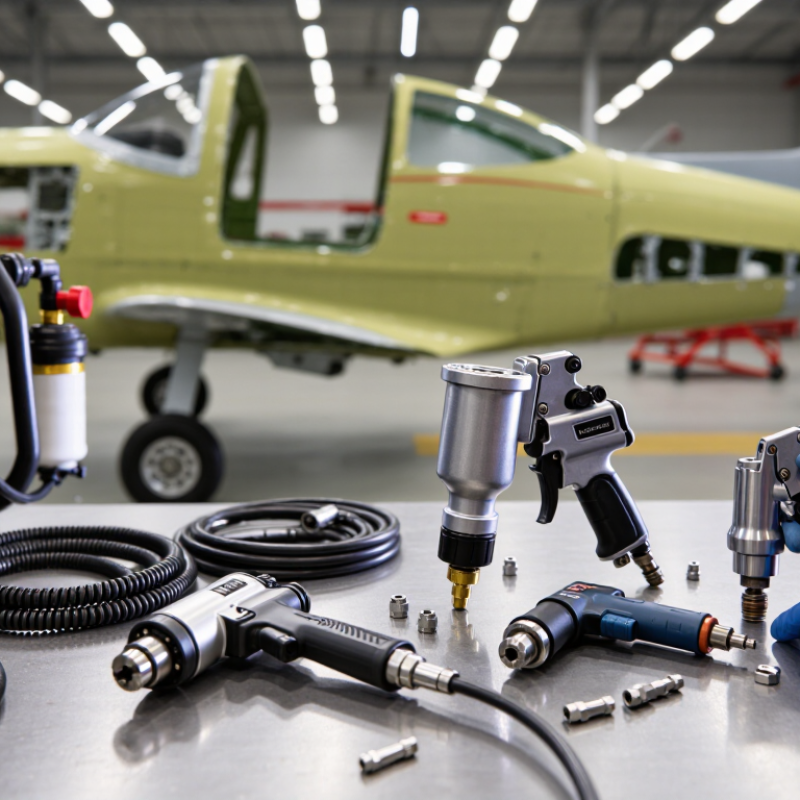
| Pneumatic Drill |
Drilling aluminum structures, brackets, skins, and aircraft interior components. |
3,000–3,500 rpm for general drilling; compact right-angle models for restricted access. |
Common chuck capacities include 6.35 mm (1/4 in) and 10 mm (3/8 in). Select a tool with sufficient torque for the approved drill-bit size and material. |
Prefer low-profile bodies, balanced weight distribution, a variable-speed trigger, and a reversible control when the maintenance task permits it. |
Use eye protection, hearing protection where required, a guarded chuck, secure workholding, and an approved air hose with whip-check protection. |
Check vibration data using the measurement approach described in ISO 28927-5. Confirm that the tool is compatible with the aircraft maintenance data and approved process. |
Preferred for routine drilling |
| Pneumatic Rivet Squeezer |
Installing solid rivets in accessible sheet-metal joints without repeated hammer impacts. |
Typical throat depths: approximately 76–305 mm (3–12 in), depending on the frame and application. |
Choose a model with adjustable ram travel and adequate rated force for the specified rivet diameter and material combination. |
Use a balanced frame, comfortable handles, low trigger force, and adjustable jaw alignment to reduce wrist deviation and hand fatigue. |
Keep fingers clear of the jaws, use correct dies, inspect the yoke and ram, and isolate the air supply before adjustment or die replacement. |
Verify the riveting procedure against the aircraft or component maintenance instructions. Tool capability does not replace required inspection criteria. |
Preferred for controlled access |
| Pneumatic Rivet Gun |
Driving solid rivets where access, structure, or joint geometry prevents the use of a squeezer. |
Common piston sizes include approximately 10.2–15.9 mm (0.401–0.625 in); operating frequency varies by model. |
Use only the rivet size, bucking method, and impact setting specified by the approved maintenance procedure. |
Select a low-vibration design with a controllable trigger, suitable grip diameter, and the lowest practical mass for the task. |
Hearing protection is normally essential because impact tools can produce hazardous noise. Use a properly fitted rivet set and maintain positive control of the tool. |
Assess hand-transmitted vibration according to ISO 28927-10 where applicable. Evaluate noise exposure against local occupational limits, including OSHA 29 CFR 1910.95 or equivalent rules. |
Use when access requires impact riveting |
| Pneumatic Impact Wrench |
Removing or installing selected fasteners during heavy maintenance, subject to approved torque procedures. |
Typical drive sizes: 6.35 mm (1/4 in), 9.5 mm (3/8 in), and 12.7 mm (1/2 in). |
Impact torque is not a substitute for calibrated final torque. Use the tool only within its rated torque and fastener-size range. |
Prefer a compact, low-reaction model with a forward/reverse selector and a grip that limits excessive wrist torque. |
Use impact-rated sockets, inspect sockets for damage, keep hands away from pinch points, and disconnect air before servicing. |
Final tightening must be performed with a calibrated torque tool when required by the maintenance data. Record calibration status in accordance with the organization’s quality system. |
Use for removal or controlled pre-tightening |
| Pneumatic Die Grinder |
Deburring, blending, surface preparation, and localized material removal. |
Common free speeds range from 18,000 to 30,000 rpm; select the speed according to the accessory rating. |
Use accessories whose maximum rated speed is equal to or greater than the tool’s free speed. Collet sizes commonly include 3 mm and 6 mm. |
Choose a slim body, low vibration, effective throttle control, and a configuration that minimizes awkward wrist angles. |
Use a guard where required, face and eye protection, respiratory controls for generated dust, and suitable hearing protection. |
Noise and vibration should be evaluated using ISO 15744 and ISO 28927 methods where applicable. Follow abrasive-wheel and accessory safety instructions. |
Suitable for controlled material removal |
| Pneumatic Angle Grinder |
Grinding or blending larger areas when the approved repair procedure permits abrasive processing. |
Common wheel sizes include 76 mm (3 in), 102 mm (4 in), and 115 mm (4.5 in). |
Confirm spindle speed, wheel diameter, wheel type, and air consumption before matching the tool to the abrasive accessory. |
Use a side handle where provided, maintain a neutral wrist position, and select the lightest tool that meets the required duty cycle. |
Use the correct wheel guard, face shield plus safety glasses, hearing protection, and dust or fume controls. Inspect wheels before use. |
Apply the manufacturer’s accessory requirements and applicable local abrasive-tool regulations. The repair method must be authorized by the applicable aircraft data. |
Requires strict process control |
| Pneumatic Nutrunner |
Repeated installation of nuts or bolts where production consistency and controlled fastening are required. |
Select the drive size and torque range to cover the specified fastener without routinely operating at the extreme end of the tool’s capacity. |
Use a torque-controlled or shut-off configuration when the approved process requires repeatable tightening. |
Consider reaction-arm design, tool balance, trigger force, noise, vibration, and the number of fasteners per shift. |
Control reaction torque, protect against unexpected start-up, inspect sockets, and use a suitable hose routing method to avoid trip hazards. |
Verify calibration and measurement-system control under ISO 6789 where hand torque tools are used for final verification. Follow the organization’s calibration procedure for powered tools. |
Preferred for repeatable fastening |
| Pneumatic Needle Scaler |
Removing corrosion, coatings, or deposits from approved metal surfaces before inspection or treatment. |
Needle diameters and operating frequencies vary widely; match the needle set to the surface and approved repair method. |
Use the minimum effective impact setting to avoid unnecessary substrate damage or excessive surface roughness. |
Select a vibration-reduced model with an insulated grip and manageable mass; rotate tasks to limit cumulative exposure. |
Use eye, face, hearing, and respiratory protection as required. Control flying particles and verify that nearby components are protected. |
Assess hand-arm vibration using ISO 28927-8 where applicable and compare daily exposure with local occupational exposure action values. |
Use only on approved surfaces |
| Air Supply and Hose System |
Providing clean, regulated compressed air to pneumatic aircraft tools. |
Many tools are designed around approximately 6.2 bar (90 psi) dynamic inlet pressure; always follow the tool specification. |
Size the compressor, receiver, filter, regulator, and hose for the tool’s actual air-consumption requirement and duty cycle. |
Use lightweight, flexible hoses with swivels where appropriate. Route hoses overhead or along protected paths to reduce trip and snag hazards. |
Use filtration, regulated pressure, couplers with positive locking, whip checks, leak inspections, and isolation before maintenance. |
Compressed-air systems should follow applicable local pressure-equipment and workplace-safety requirements. Never use compressed air to clean clothing or the body. |
Mandatory system check |
| Noise and Vibration Program |
Managing cumulative exposure from drilling, riveting, grinding, and impact operations. |
Measure actual workplace exposure rather than relying only on catalog values; exposure depends on trigger time, tool condition, and task method. |
Record sound pressure, sound power where available, and three-axis vibration values when supplied by the tool manufacturer. |
Prefer low-noise and low-vibration tools, schedule task rotation, provide breaks, and avoid prolonged gripping force. |
Implement hearing conservation where required. OSHA uses an 8-hour permissible exposure limit of 90 dBA with a 5 dB exchange rate; local rules may differ. |
Use ISO 15744 for noise-emission measurement and ISO 28927 series methods for vibration measurement where applicable. Apply the stricter legal requirement when jurisdictions differ. |
Required for safe long-term use |
| Aircraft Maintenance Documentation |
Ensuring that tool selection and use remain consistent with approved maintenance instructions. |
Confirm task-specific limits before selecting speed, pressure, torque, accessory, rivet type, or surface-treatment method. |
Tool capability must be compatible with the aircraft maintenance manual, structural repair manual, component maintenance manual, or other approved data. |
Include human-factors considerations such as access, visibility, posture, reach, fatigue, and the need for a second technician. |
Document inspections, calibration, training, personal protective equipment, and equipment defects according to the organization’s procedures. |
FAA AC 43.13-1B may provide acceptable methods for certain civil aircraft when its applicability conditions are met; it does not override approved or mandatory aircraft data. |
Verify before every critical task |